Baseband video consists of one video picture being sent point-to-point, such as the video output of a VCR to the video input of a monitor. Figure 1 illustrates simple point-to-point transmission. There exist two levels of service for baseband video: broadcast studio and consumer. These types describe, primarily, the quality of the signal. Broadcast studio quality requires a much higher signal fidelity, while consumer quality baseband requires is less demanding. In addition to the difference in signal fidelity, there is also a difference in the connectors typically used for the transmission of these signals. The broadcast baseband applications typically use a BNC connector and the consumer baseband applications typically uses an RCA connector.
Figure 1 - Point-to-Point Transmission
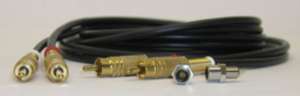
Figure 2 - BNC and RCA Connectors
Baseband Video Signals
The most basic form of a television signal is a baseband video signal, also referred to as a composite video signal. In an AM baseband system, the input signal directly modulates the strength of the transmitter output, in this case light. The baseband signal contains information relative to creating the television picture only. The following information is carried on a baseband signal:
• Scanning: drawing the television picture
• Luminance: the brightness of the picture
• Chrominance: the color of the picture
The creation of the baseband signal produces a range of frequency components. The highest frequency in a baseband signal is also its bandwidth. The lowest frequency ranges close to zero Hz or DC. The video output of a television camera or video tape recorder has its highest frequency, therefore, its bandwidth, at either 4.2 or 6 MHz, depending on the type of TV format used. Looking at an actual baseband signal, illustrated in Figure 3, we can see that the camera and the video display are scanned horizontally and vertically. The horizontal lines on the screen are scanned alternately, with the odd numbered lines first and the even numbered lines second, or vice versa. (Figure 3B depicts the initial scan of the odd numbered lines.) This method is known as an interlacing system. The second method is to scan the lines sequentially; this is known as progressive Scanning. The camera and receiver must be synchronized when scanning and reproducing an image. The horizontal and vertical sync pulses regulate the synchronization of the camera and receiver, illustrated in both 3B and 3C, and starts a horizontal trace. As seen in Figure 3A, during the horizontal blanking interval, the beam returns to the left side of the screen and waits for the horizontal sync pulse before tracing another line. The dotted line illustrated the horizontal retrace. When the beam reaches the bottom of the screen, it must return to the top to begin the next field. This is called the vertical retrace, which is signaled by the vertical sync pulse illustrated in Figure 3C. The vertical retrace takes much longer than the horizontal retrace, therefore, a vertical blanking interval ensues to synchronize the two signals. During both the horizontal or vertical blanking intervals no information appears on the screen.
Figure 3 - Baseband Composite Video Signals
Baseband Video Applications
Figure 4 illustrates a multimedia baseband fiber optic transmission systems.
Figure 4 - Multimedia baseband transmission
This artical is from: http://www.voscom.com/trainning/baseband-video-transmission.asp
No comments:
Post a Comment