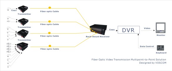
Fiber optics for CCTV applications are predominantly used in extended local installations linking cameras back to monitors with dedicated fibres for each link. A typical fiber optic transmission system layout is shown in Fig. 6.
This example illustrates the main features of any fibre optic system, which are as follows:
1. The fibre optic link and its associated terminal equipment fit between the camera and the associated monitor/controller and provide a transparent signal path i.e. the camera and controller do not know that the signals have been transmitted over fiber.
2. The camera output is a 1V peak to peak composite video signal.
3. Movable cameras have a telemetry receiver is mounted near to the camera movement mechanism. This telemetry receiver connects to the system controller to provide control of the camera pan/tilt and zoom PTZ functions.
4. At the control end of the link camera selection and movement is looked after by the system controller and video signal outputs from the controller are displayed on a local monitor(s).
5. Electrical to optical and optical to electrical converters provides the interfaces to the optical fibre transmission fibre.
6. At the camera end of the link the E/O converter is usually a single channel unit packaged in a small enclosure which can be conveniently mounted near to the camera or telemetry receiver. These E/O converters are not usually environmentally sealed and so need to be protected from the elements often mounting them in the telemetry receiver enclosure. In their most cost effective form a PTZ cameras E/O converter will use two multimode fibres to give a uni-directional video connection plus a bi-directional control data channel.
7. As an alternative these control and video link functions can be carried over a single fibre using optical transmission at two wavelengths, WDM – wavelength division multiplexing. These WDM links are more expensive than single wavelength links but they do save on fibre usage and they also can make the best use of a previously installed fibre infrastructure.
8. The E/O converter data interface must be compatible with that used by the system controller; these are often non-standard.
9. Fixed cameras can use a miniature E/O transmitter, which can connect directly to the camera BNC signal output. This link requires only one fibre.
10. The camera end E/O converter is connected to the transmission fibre through a patch box. This patch box provides a point of termination for the transmission cable and so prevents strain and wear and tear being placed on the transmission cable when installing, servicing or moving the terminal equipment. Optical connections between the E/O converter and the patch box are made with duplex patchleads (which are short fibre cable lengths terminated at each end with an optical connector). The patch box will only be a relatively small enclosure because it will only need to provide connectivity for a few fibre cores.
11. At the control room end of the link fibres from a large number of cameras will be concentrated. Equipment must therefore be packaged accordingly and most often this means the use of 19” rack mount units. E/O converters are manufactured in modular card format, which enables multiple video channels to be accommodated in a 19” cage. Typically one 3 U high rack can accept plug-in E/O converters for up to 30 video only channels or 10 video/data channels (or a mixture of both).
12. The fibre transmission cables are also handled in 19” rack enclosures because now we will be organising many fibre cores. These enclosures are called patch panels and they again provide a physical buffer between the transmission cable and the terminal equipment. Here the cable will be bought into the rear of the patch panel via a compression gland and the fibre cores will be broken out into the secondary coated cores. These cores will then be terminated with connectors, which are then connected into in-line adaptors mounted through the front bulkhead of the patch panel enclosure. This termination may either be carried out by the direct attachment of connectors to the fibre tails or factory terminated connectors tails will be spliced to the transmission fibre cores. If splices are used then the splice enclosures will be mounted in clips on the patch panel base. Patchleads then connect the patch panel bulkhead connections to the E/O converter optical connections. Copper leads then complete the connections to the system
controller and monitors.
As part of the cable installation the installer will have measured the installed cable loss, a function of position using a piece of test equipment called an OTDR (Optical Time Domain Reflectometer). This measurement serves to finger print the system and provides a point of reference for future system maintenance. It also provides the value of the end to end loss of each optical fibre used. The total loss must not exceed the optical margin specified by the equipment manufacturer, otherwise the transmitted picture quality may be impaired. In a correctly installed multimode system link lengths of 4 km for 850nm products and 8 km for 1300nm products are readily achieved.
No comments:
Post a Comment